Control components
CIO - CANopen input-output module
Customised solutions thanks to modular expansion components
Various expansion components are available to optimally adapt the lift controller to the respective application. These are connected to the control system using a CAN bus with the CANopen lift standard.
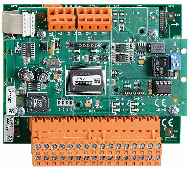
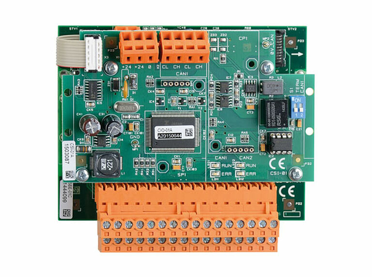
The CAN-I/O module makes 32 calls available via the CANopen bus.
Status LEDs facilitate initial rapid diagnosis of the CAN bus.
| Mechanical data | |
| Dimensions in mm: W x H x D | 120 x 110 x 50 with RS485 Schnittstelle: 120 x 110 x 70 |
| Mounting: | Quick fastening for standard rail according to EN 60715 |
| Electrical data | |
| Ports | 32 Calls, outputs short-circuit-proof |
| Rated operational voltage: | 24 VDC +20 %/-20 % |
| Current consumption max.: | 50 mA |
| Input current | 7 mA |
| Output current max.: | 500 mA per output 500 mA in sum of all outputs |
| Possible extension: | via 10-pin ribbon cable to SBE |
| Display elements | |
| Status-LED(RUN): | green, in standard operation always on |
| Error-LED(ERR): | red, in standard operation always off |
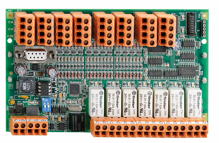
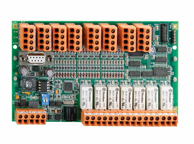
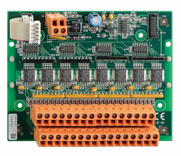
For transmission of the lift car signals via the CANopen bus to the processor Status LEDs facilitate initial rapid diagnosis of the CAN bus SUB-D 9-pin interface for CANopen absolute value sender can be extended to 32 calls with CLE-01A.
| Mechanical data | |
| Dimensions in mm: W x H x D | 115 x 90 x 50 without snap-in base and femal connectors: 115 x 90 x 15 |
| Mounting: | Quick fastening for standard rail according to EN 60715 or mounting holes for self-fixing |
| Electrical data | |
| Ports | 16 Inputs, 8 Outputs, 8 Calls, 1 NC,4 NO, 2 change over contacts, Outputs short-circuit-proof |
| Relais: | |
| 3 x Relais | 24 VDC, 6 A, 1 changeover contact |
| 4 x Relais | 24 VDC, 6 A, 1 normally open contact |
| Rated operational voltage: | 24 VDC +10 %/-15 % (PELV) |
| Protection: | fused with 1.1A multifuse |
| Inputs/outputs: | |
| Input current | 3,8 mA |
| Max. output current: | 500 mA per output 500 mA in sum of all outputs |
| Assembly group: | |
| Power consumption typ: | 25 mA |
| Possible extension: | via 10-pin ribbon cable to CLE |
| Display elements | |
| Status-LED(RUN): | green, in standard operation always on |
| Error-LED(ERR): | red, in standard operation always off |
For extending CLK to 32 calls.
| Mechanical data | |
| Dimensions in mm: W x H x D | 115 x 90 x 45 |
| Mounting: | Quick fastening for standard rail according to EN 60715 |
| Electrical data | |
| Ports | 32 Calls, outputs short-circuit-proof |
| Rated operational voltage: | 24 VDC +20 %/-20 % |
| Current consumption max.: | 50 mA |
| Input current | 7 mA |
| Output current max.: | 500 mA per output 500 mA in sum of all outputs |
| Possible extension: | via 10-pin ribbon cable to SBE |
| Display elements | |
| Status-LED(RUN): | SMD on: operating voltage available |

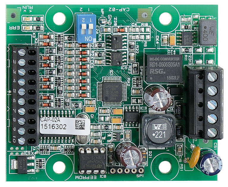
For coupling two CANopen strands.
| Mechanical data | |
| Dimensions in mm: W x H x D | 120 x 80 x 30 |
| Mounting: | Quick fastening for standard rail according to EN 60715 |
| Connection type: | Spring clamp terminals |
| Cable section: | with wire end ferrule 0,25-1,5 mm² |
| Connection cable: | rigid or flexible |
| Electrical data | |
| Rated operational voltage: | 24 VDC +20 %/-20 % |
| Current consumption typ.: | 35 mA |
| Display elements | |
| Status-LED(RUN): | green, in standard operation always on |
| Error-LED(ERR): | red, in standard operation always off |
Serves to actuate exterior panel via CANopen bus.
| Mechanical data | |
| Dimensions in mm: W x H x D | 63 x 76 x 13 |
| Mounting: | for installation / four holes provided for M4 |
| Electrical data | |
| Rated operational voltage: | 24 VDC +20 %/-20 % |
| Current consumption typ.: | 25 mA |
| Input current | 3,8 mA |
| Output current max.: | 500 mA per output 500 mA in sum of all outputs |
| Display elements | |
| Status-LED(RUN): | green, in standard operation always on |
| Error-LED(ERR): | red, in standard operation always off |
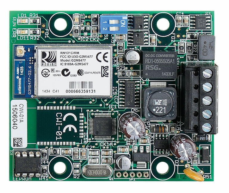
For access via WLAN to CANopen bus WLAN-capable end device required (smartphone, tablet, ...) In housing as an option (CWI-01G).
| Mechanical data | |
| Dimensions in mm: W x H x D | 63 x 76 x 13 |
| Mounting: | Hole max. M4 |
| Connection type: | Screw terminals |
| Cable section: | with wire end ferrule 0,25-1,5 mm² |
| Connection cable: | rigid or flexible |
| Electrical data | |
| Rated operational voltage: | 24 VDC +20 %/-20 % |
| Current consumption typ.: | 30 mA |
| Display elements | |
| Status-LED(RUN): | green, in standard operation always on |
| Error-LED(ERR): | red, in standard operation always off |
To fulfil normative requirements, safety components can be used to supplement and modernise the lift control system. These components fulfil the safety functions specified in EN 81-20 and are type-tested.
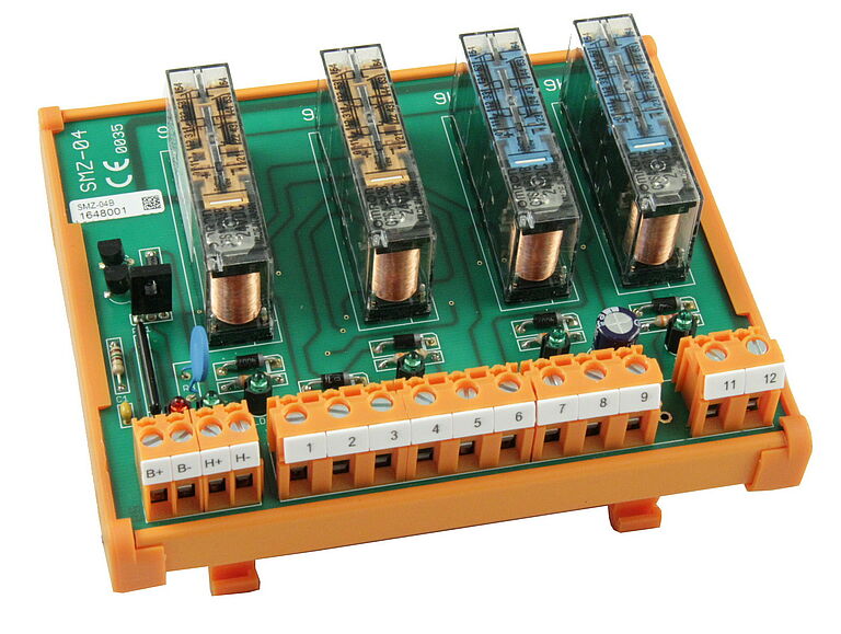
The SMZ safety switching module has a two-channel safety circuit that monitors both signals for synchronised switching.
| Mechanical data | |
| Dimensions in mm: W x H x D: | 129 x 110 x 80 |
| Mounting: | Quick fastening for standard rail according to EN 60715 |
| Installation position: | To be mounted horizontally on a vertically installed mounting plate in a control cabinet |
| Connection type: | Screw terminals |
| Cable section: | with wire end ferrule 0,25-2,5 mm² |
| Connection cable: | rigid or flexible |
| Mechanical lifetime: | 10 million switching cycles |
| Shock resistance: | 10 g / 11 ms |
| Vibration resistance according to EN 60068-2-6: | 10 … 11 ms amplitude 0,35 mm |
| Electrical data | |
| Rated operational voltage: | 24 VDC +10 %/-15 % (PELV) |
| Current consumption max.: | max. 200 mA |
| Input current: | 20 mA |
| Switching voltage: | max. 48 V DC; max. 250 V AC |
| Switching and continuous current: | max. 2 A |
| Switching capacity: | max. 1000 VA; max. 75 W |
| Reaction Time switch off Zone Relais: | max. 10 ms |
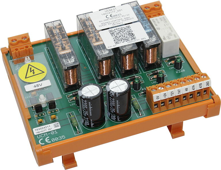
The UCM module contains a circuit for detecting unintentional car movements when the doors are open in accordance with EN 81-20. It can be used in combination with a certified anti-drop device on the overspeed governor and a certified safety gear to protect against unintentional car movement.
| Mechanical data | |
| Dimensions in mm: W x H x D | 129 x 110 x 80 |
| Mounting: | Quick fastening for standard rail according to EN 60715 |
| Installation position: | To be mounted horizontally on a vertically installed mounting plate in a control cabinet |
| Connection type: | Screw terminals |
| Cable section: | with wire end ferrule 0,25-2,5 mm² |
| Connection cable: | rigid or flexible |
| Mechanical lifetime: | 10 million switching cycles |
| Shock resistance: | 10 g / 11 ms |
| Vibration resistance according to EN 60068-2-6: | 10 … 11 ms amplitude 0,35 mm |
| Electrical data | |
| Rated operational voltage: | 24 VDC +10 %/-15 % (PELV) |
| Current consumption max.: | max. 200 mA |
| Input current: | 20 mA |
| Switching voltage: | max. 48 V DC; max. 250 V AC |
| Switching and continuous current: | max. 2 A |
| Switching capacity: | max. 1000 VA; max. 75 W |
| Reaction Time switch off Zone Relais: | max. 10 ms |
Electronic control components that are used in the complete control system, but which do not require CAN bus communication but are electrically integrated, are also available for optimum supplementation.
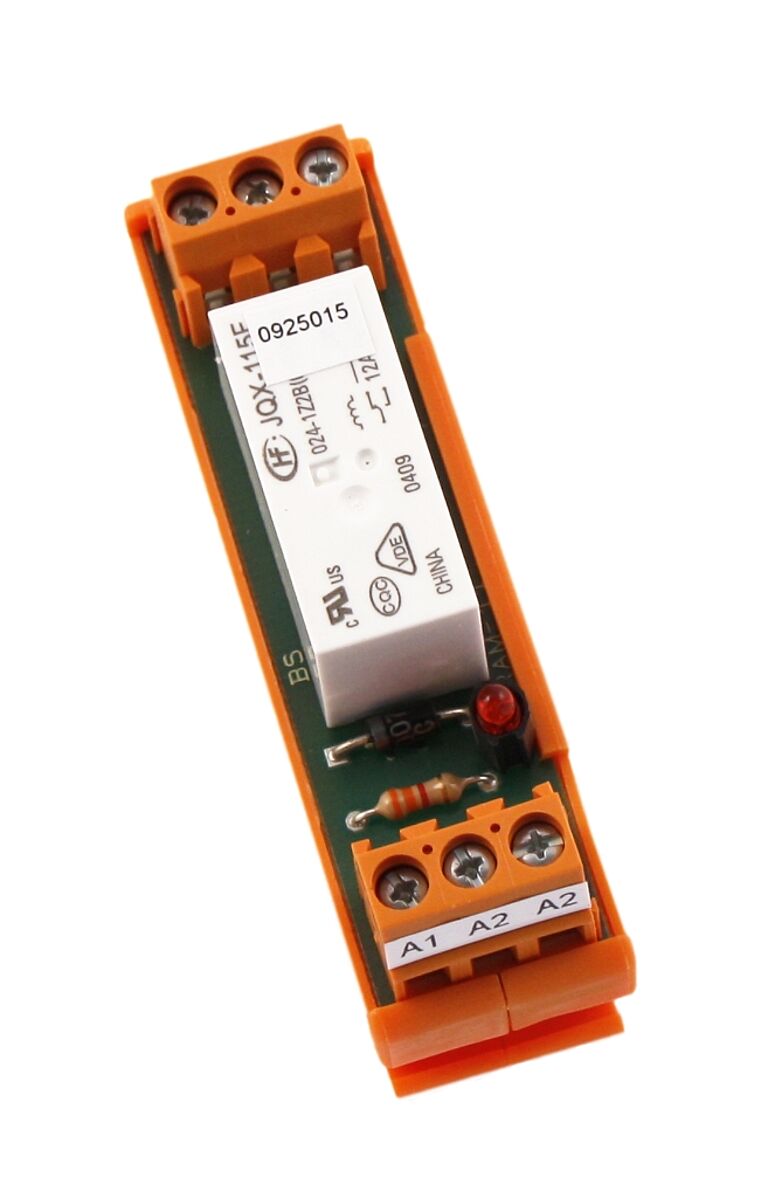
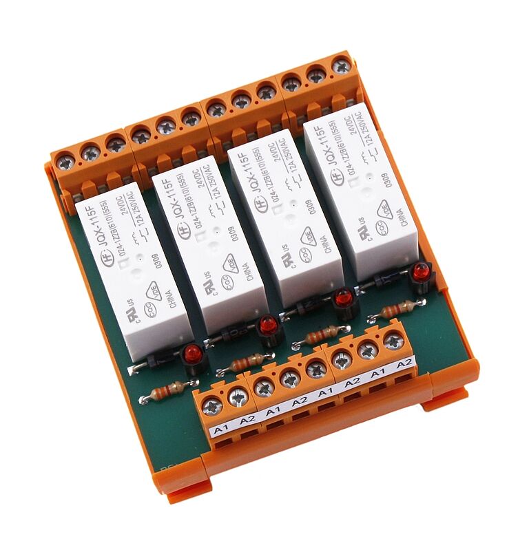
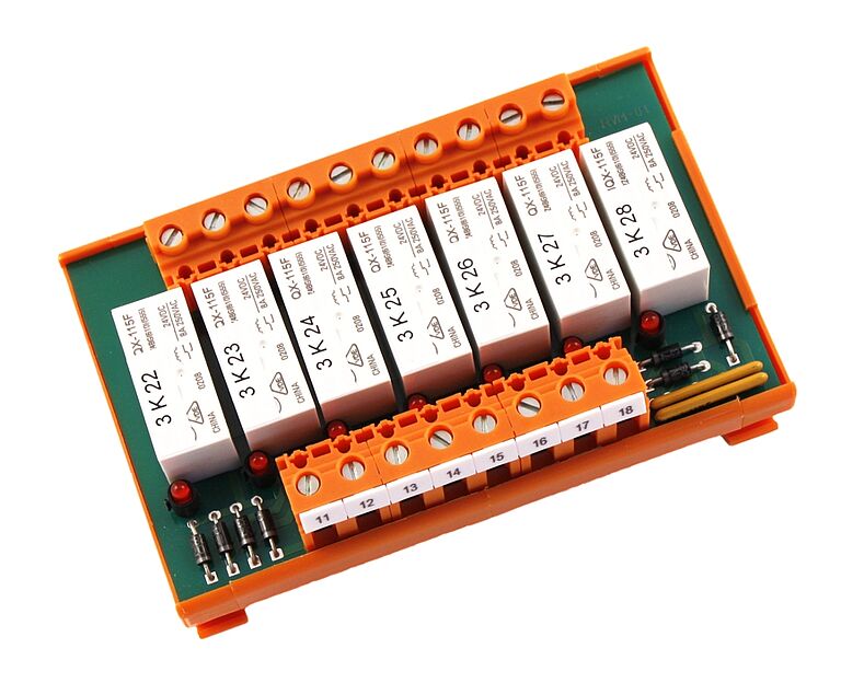
Variants with one, two or four changeover contacts available in different voltages.
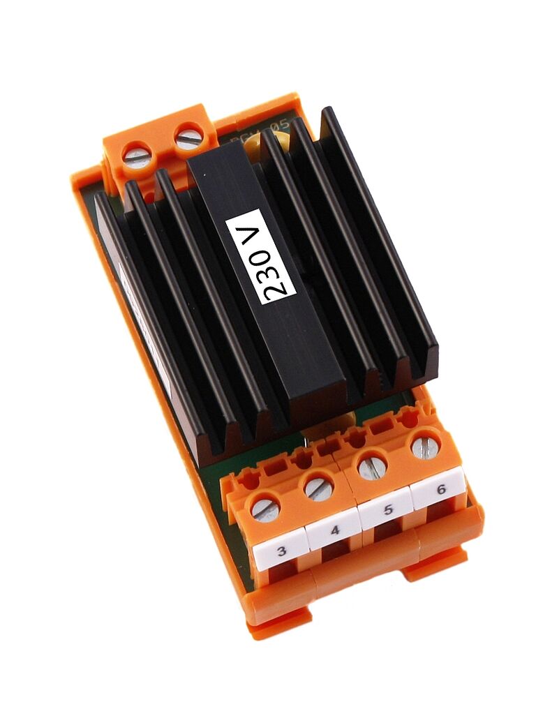
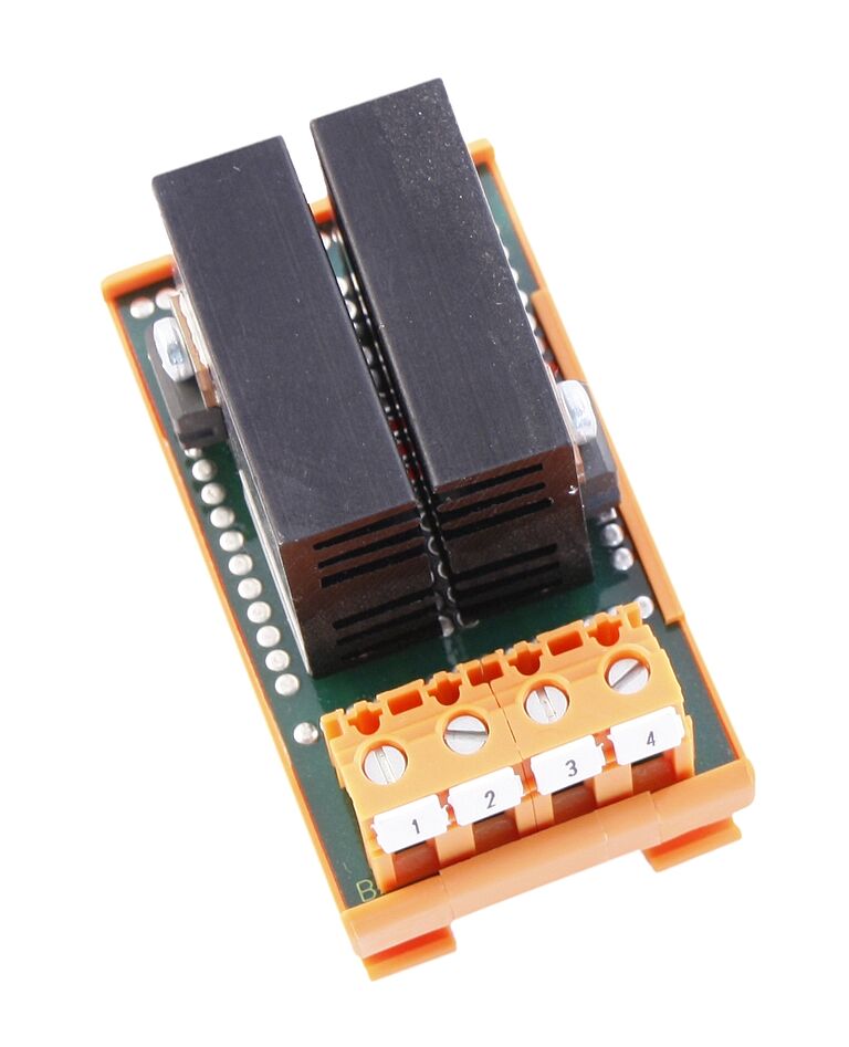
Module for generating the DC brake voltage.
Parallel control of all known drive devices.
For rectifying low AC voltages or decoupling DC voltages.
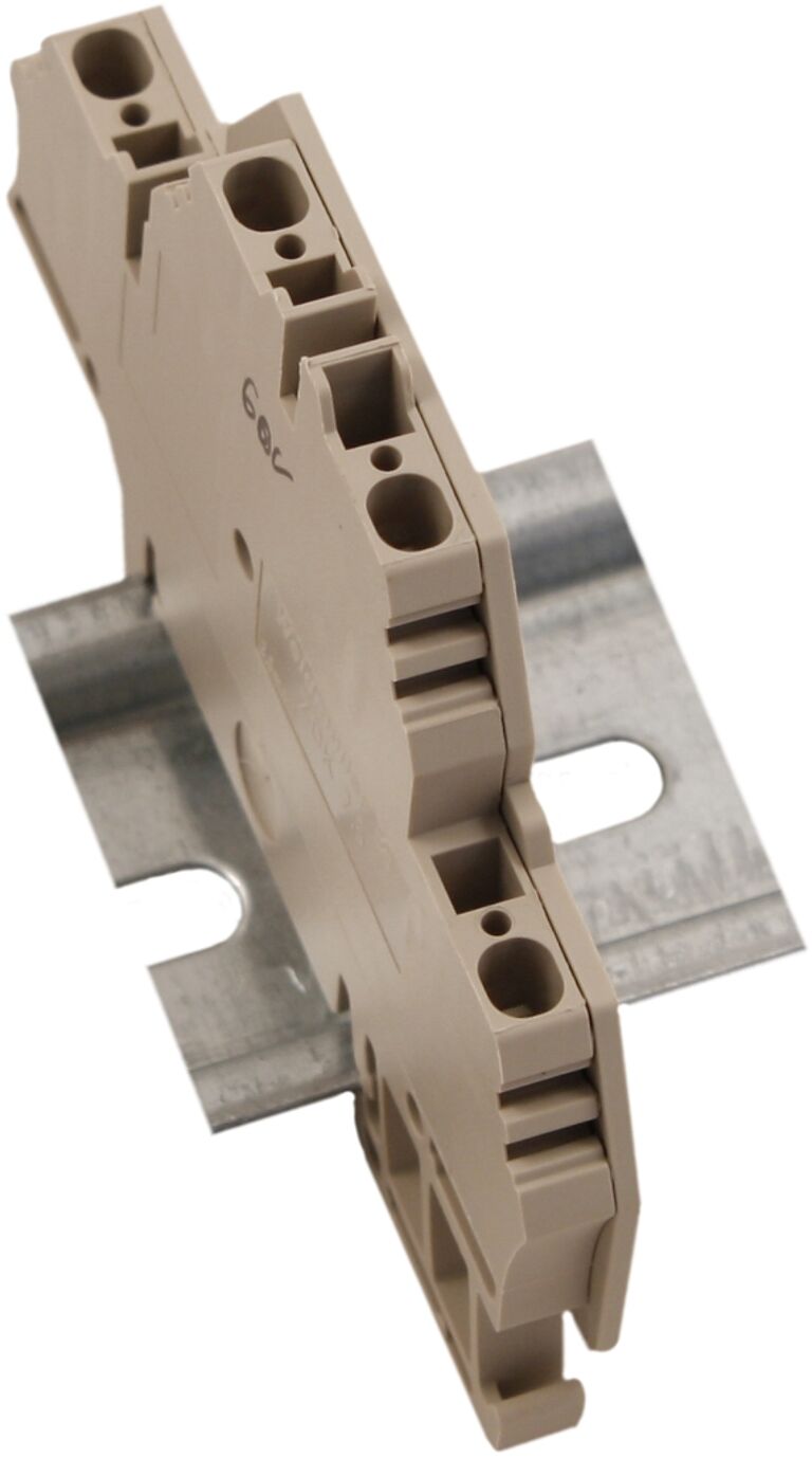
For suppression of interference peaks.
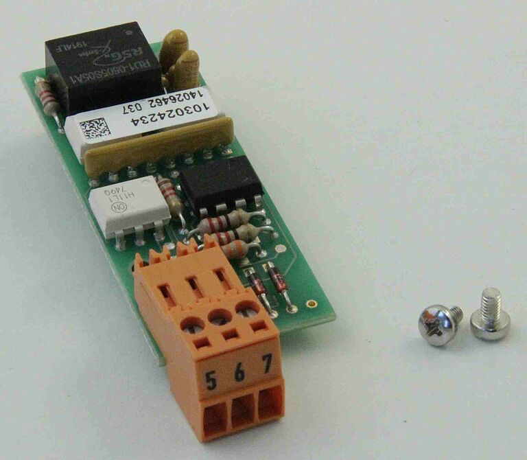
Signal level converter module for converting TTL signals.
